
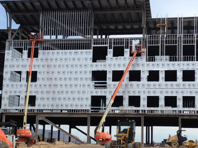
Moisture problems often start where wall systems are interrupted. Weak joints, flashing gaps, penetrations, and poorly coordinated layers can let water in or leave it with nowhere to drain or dry. Moisture-resilient wall systems are designed so water has a way out at every one of those points.
What Makes Moisture Resilient Wall Systems Work?
A moisture-resilient wall manages how water enters, moves through, drains from, and dries out of the assembly. Moisture-resistant materials can support that goal, but no single board, membrane, or insulation product can compensate for broken flashing, uncontrolled air leakage, trapped water, or discontinuous control layers.
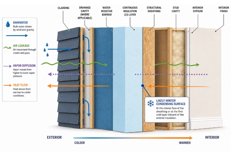
The design has to manage bulk water, capillary movement, air-transported moisture, and vapor diffusion, then account for where condensation can occur and how incidental moisture will drain or dry. A good design gives each job to a specific layer, or a tested combination of layers, and keeps those layers continuous across the wall. Assembly-level wall moisture management also depends on temperature, because a warmer surface is less likely to reach conditions where condensation can occur.
Control Rain Before It Reaches Moisture-Sensitive Layers
At the exterior, cladding, drainage, the WRB, and flashing work together to manage rain before it reaches moisture-sensitive layers.
Create a Drainage Path
Cladding sheds rain at the exterior, but wall design should assume that some water can pass through joints, laps, or penetrations and provide a clear route for that water to drain back out.
A drainage space separates wet cladding from layers deeper in the wall and can also act as a capillary break by interrupting direct liquid-water contact between adjacent materials. Behind that space, the water-resistive barrier (WRB) provides a secondary line of defense, and flashing connects openings, penetrations, and intersections back to the drainage path.
Coordinate the All Control Layers
A continuous air barrier limits airflow through joints and penetrations, vapor-control materials regulate diffusion according to climate and assembly needs, and exterior continuous insulation helps control temperatures deeper in the wall. Some tested systems can perform several functions with fewer physical layers. In the RMAX ECOMAXci Wall Solution, continuous insulation, sealed joints, and compatible flashing components work together as part of a tested air and water barrier assembly.
During design review, trace each control layer across the wall and through every opening, penetration, and transition. If you cannot follow the water, air, thermal, or vapor strategy continuously across the drawings, the detail needs to be resolved before construction begins.
How Can Continuous Insulation Reduce Condensation Risk?
Exterior continuous insulation helps control condensation risk by changing the temperature profile through the wall. It reduces heat flow through studs and other framing members by carrying the thermal layer across them. Using continuous insulation on the exterior can also keep sheathing warmer during cold conditions, which can reduce condensation potential at that surface.
Climate, indoor humidity, the amount of exterior insulation, cavity insulation, air leakage, and vapor-control strategy all influence temperature and moisture conditions inside the wall. That makes exterior insulation one part of the condensation strategy, not a guarantee against it. Exterior polyiso continuous insulation can improve thermal continuity without requiring cavity insulation to carry the full thermal load. The location and amount of insulation affect the temperature profile through the wall, which can shift condensation risk from one surface or layer to another under a given set of conditions.
Give Incidental Moisture a Way Out
A durable wall should limit unwanted wetting and still provide a realistic path for incidental moisture to drain or dry. Cladding, flashing, drainage, the WRB, and sealed penetrations reduce water entry, but the assembly also needs to account for rain that gets behind cladding, construction moisture, small leaks, and vapor that enters through diffusion or air movement.
Drying potential depends on the surrounding layers giving that moisture a practical route out. A drainage path removes liquid water, while suitable material placement allows remaining moisture to dry under favorable conditions. That's the core idea behind moisture-resilient wall systems: assume the wall will get wet, and plan how it dries.
How Does Climate Affect Vapor Control and Drying?
Climate changes the temperature and humidity conditions across a wall, so there is no universal vapor-control strategy that is correct for every assembly. Cold conditions can make exterior sheathing more vulnerable to condensation from interior moisture. In warm-humid conditions, rain-wetted absorptive claddings can create strong inward vapor drives when solar heating raises their temperature.
Material placement matters as much as material properties. Vapor permeance describes how readily water vapor passes through a material, but its effect changes with location in the wall, the layers on either side, and the direction the assembly needs to dry. Low-permeance layers can help control vapor movement, but they should not be placed where they leave moisture-sensitive materials with no practical drying path. Set the vapor strategy and the thermal design together. Exterior insulation shifts temperatures in the wall, but you still need to check drying potential before deciding where vapor resistance goes.
Keep Every Control Layer Continuous at Interfaces
Once the water, thermal, air, vapor, and drying strategies are defined, they still have to survive the places where the wall is interrupted.
Coordinate Materials and Trades at Interfaces
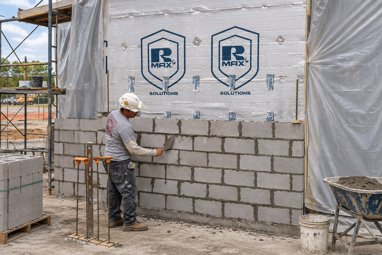
Openings, penetrations, transitions, and changes in plane are where otherwise sound wall designs are most likely to lose control-layer continuity. They’re also where several trades have to hand off work to each other.
Compatible membranes, flashing materials, tapes, sealants, and joint treatments need to be installed in an order that preserves the intended drainage and control-layer sequence. Drawings and specifications should make it clear which layer each trade is tying into and who closes the gap where adjacent systems meet.
Windows and Doors
Openings bring several control functions together in a small area. Sill, jamb, and head flashing need to connect with the water-control layer so incidental water is directed back toward the exterior, and the air-control layer must remain sealed around the perimeter.
A high-performing insulation board cannot correct a window detail that sends water behind the WRB. The finished detail needs an outward drainage path and an intact perimeter air seal.
Penetrations and Transitions
Pipes, conduits, ducts, fasteners, structural attachments, and material changes can interrupt the air, water, and thermal control layers. Each penetration needs a detail that restores the function of the layer it passes through rather than relying on sealant as an undefined cure for every condition.
Transitions deserve the same attention. Changes between wall systems, foundation conditions, parapets, floor lines, and adjacent materials should be detailed so each interrupted function is restored across the transition.
Roof-to-Wall Connections and Insulation Joints
Roof-to-wall intersections concentrate rainwater and require flashing and drainage paths that move water away from the wall assembly. Poor sequencing at these locations can allow water to bypass otherwise sound materials.
Insulation-board joints also need the joint treatment prescribed for the selected system. Open or improperly sealed joints can compromise thermal, air, or water-control functions when those roles depend on the insulation layer and its joint treatment.
Conventional Wall Assembly vs. Moisture-Resilient Wall System
A conventional wall can still perform well when it is correctly designed and detailed. Moisture resilience comes from deliberately coordinating the thermal, air, water, vapor, drainage, and drying functions across the assembly.
| Performance Area | Conventional / Primarily Cavity-Insulated Approach | Moisture-Resilient / High-Performance Approach |
|---|---|---|
| Thermal bridging | Framing creates repeating heat-flow paths through cavity insulation | Exterior CI reduces framing-related thermal bridges |
| Condensation risk | Sheathing may remain colder in winter depending on the assembly | Warmer exterior-side sheathing under applicable conditions |
| Bulk-water management | Relies on correctly connected WRB, flashing, and drainage details | Water-control and drainage paths are deliberately integrated |
| Air leakage | Air-control function may be distributed among several materials | Defined continuous air-control plane |
| Drying potential | Drying depends on layer permeance, drainage, and available inward or outward drying paths | Drying direction and recovery paths are evaluated as part of the assembly design |
| Continuous insulation | May be absent or limited | Exterior CI improves thermal continuity |
| Long-term moisture performance | Performance depends on continuity of the WRB, flashing, air control, vapor control, and insulation details | Long-term performance still depends on maintaining control-layer continuity through details, interfaces, and installation |
Moisture-Resilient Wall System Checklist
Use this checklist during design review and again before the wall is closed in. Start with bulk water and air, then work through the rest.
Bulk-water control: Identify how the cladding and backup water-control layer limit rain entry.
Drainage plane: Confirm water behind the cladding has a continuous path down and out.
Flashing: Verify windows, doors, roof intersections, and other openings direct water back to the exterior.
Continuous air barrier: Identify the primary air-control layer and confirm continuity at joints, openings, penetrations, and transitions.
Vapor control: Match the vapor strategy to the climate, wall configuration, and intended drying direction.
Continuous insulation: Maintain exterior thermal continuity across framing, board joints, transitions, and attachments.
Condensation control: Evaluate temperatures at moisture-sensitive layers rather than assuming insulation R-value alone resolves condensation risk.
Drying potential: Determine where incidental moisture can drain or dry if the assembly becomes wet.
Penetrations and transitions: Restore every required control function where another component interrupts the wall.
Climate-zone considerations: Account for local temperature, humidity, seasonal vapor conditions, and interior moisture loads.
Build a More Coordinated Wall System With RMAX
RMAX continuous insulation and tested wall-system solutions can help design teams coordinate thermal performance with specific air- and water-control functions. RMAX’s technical team can help match the product to your wall assembly and climate. Contact us today for more information.
Frequently Asked Questions
Continuous insulation, vapor control, and drying all work differently depending on how the rest of the wall assembly is designed.
-
Not automatically. A specific continuous-insulation product or tested system may be approved to perform a WRB function, but that capability must be confirmed for the selected assembly and joint treatment.
-
Not necessarily. Vapor control can range from more vapor-open materials to lower-permeance retarders depending on climate, wall design, and the drying path the assembly needs.
-
Walls need controlled drying rather than uncontrolled air leakage. The air-control layer should limit airflow through the enclosure, and the wall's vapor and drainage strategy should provide appropriate paths for moisture to leave.
-
Condensation can develop where moisture encounters a surface cold enough for the local temperature and humidity conditions. Exterior insulation can change those temperatures, so condensation risk should be evaluated for the complete wall assembly rather than assigned to one fixed location.