
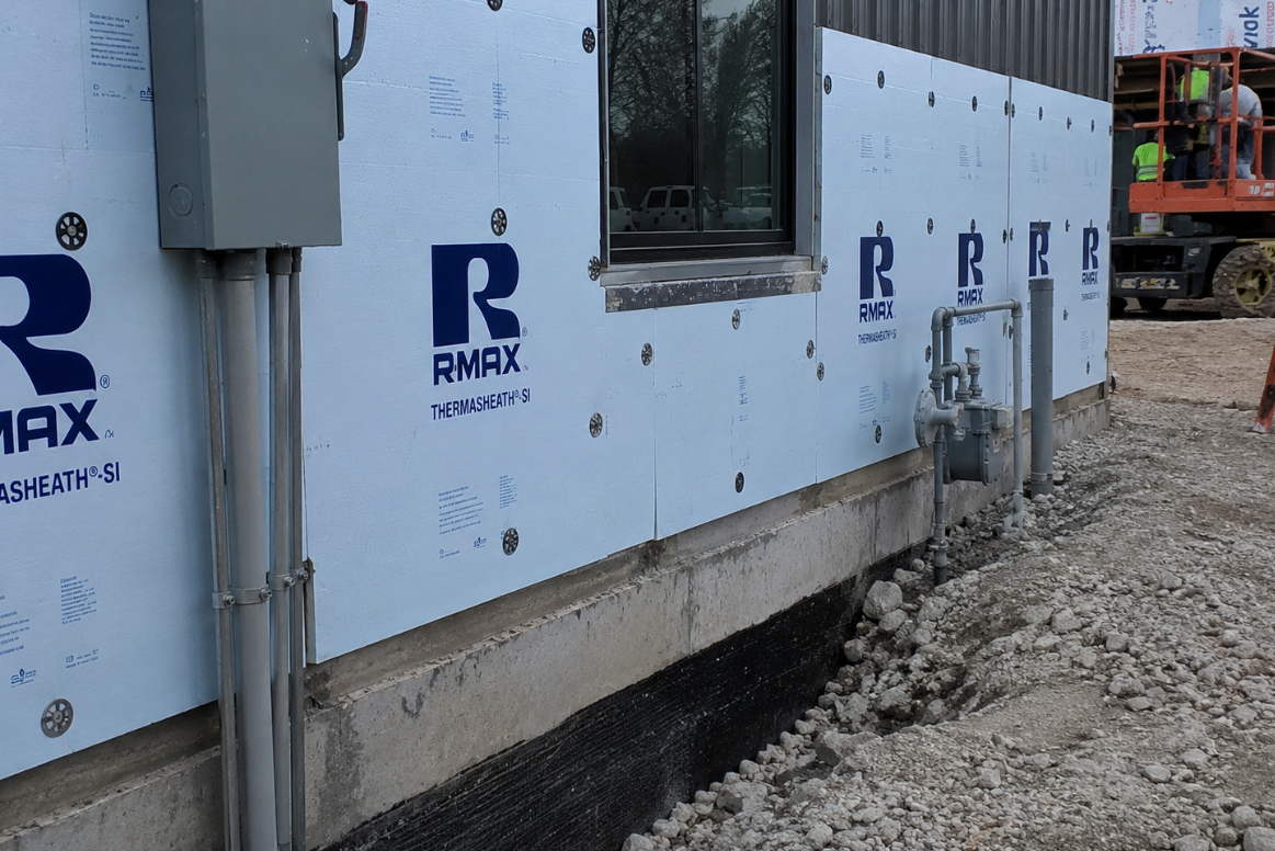
The weak spots in a continuous insulation (CI) system usually appear where the wall is interrupted. Gaps at roof lines, window perimeters, service penetrations, and cladding attachments can create heat-flow paths, air leaks, and water-management problems that are hard to fix after the wall is closed. That is why continuous insulation detailing needs to address transitions, penetrations, air and water barrier integration, and field verification before installation begins.
How Continuous Insulation Detailing Protects Envelope Performance
The strongest details make each layer’s job clear before the assembly reaches the field.
Control-Layer Alignment
Continuous insulation detailing protects envelope performance by keeping the insulation layer aligned with the control layers responsible for thermal resistance, air control, water management, and durability. Thermal continuity is the starting point, but the finished assembly also has to manage air leakage, bulk water, vapor behavior, cladding attachment, and movement between materials. Those priorities become most visible at transitions and penetrations in continuous insulation systems, where flat-wall assumptions meet openings, supports, and service pathways.
Continuous insulation is intended to reduce heat flow through framing and other repetitive structural members. In practice, continuous insulation performance depends on how the exterior thermal layer works with the full wall assembly, including board R-value, framing, attachment, air leakage, and installation quality. Details determine whether the specified wall strategy holds together at openings, corners, floor lines, penetrations, and attachment points.
Buildability and Inspection
Well-resolved details also make the work easier to build and inspect. A useful CI detailing guide should show where the insulation continues, where the air barrier connects, where the water-resistive barrier laps, where flashing drains, and how cladding support transfers loads back to structure. When those items are resolved together, the field team has a clearer path to a durable installation.
Common Continuous Insulation Transition Details
Transition details deserve early attention because the thermal layer, air barrier, WRB, flashing, structure, and cladding support have to connect where multiple enclosure systems meet.
Roof-to-Wall Transitions
Parapets and similar upper-wall conditions all raise the same practical question: how does the thermal layer continue when the wall is no longer simple and uninterrupted?
At roof-to-wall transitions, the detail has to align wall insulation with the roof assembly, air barrier tie-ins, membrane terminations, and drainage. If the wall insulation stops short of the roof insulation, the assembly may create a linear thermal bridge. If the air barrier connection is unclear, the same transition can become an air leakage path.
Base-of-Wall and Foundation Transitions
Base-of-wall and wall-to-foundation details need the same level of planning. The insulation termination, flashing, drainage path, slab or foundation interface, and air-control transition all have to work together at a location that often sees splashback, grade changes, and trade sequencing conflicts.
Openings, Shelf Angles, and Structural Attachments
Window and door openings create a different challenge. The rough opening needs insulation return details, flashing, air sealing, WRB continuity, and drainage that moves water outward. A detail that shows only the insulation board layout is incomplete because the opening still has to shed water and connect to the air-control strategy.
Shelf angles, balconies, clips, and brackets require special attention because they connect exterior systems back to structure. These details may be necessary for cladding support or structural function, but they can also create concentrated thermal bridges if they are not reviewed as part of the envelope design. The practical goal is to reduce unnecessary interruptions and manage the ones the project requires.
Detailing Around Wall Penetrations
Wall penetrations interrupt more than insulation, so the detail has to address every control layer affected by the opening.
Plan Penetrations Before Installation
Wall penetrations should be planned before installation so the insulation, air barrier, WRB, sealant, flashing, and attachment strategy work as one detail. Pipes, ducts, conduit, electrical boxes, sleeves, anchors, and brackets all interrupt one or more control layers. Repeated small openings can add up to meaningful heat loss and leakage paths across a facade.
Restore Each Control Layer
Penetration detailing for continuous insulation should define the insulation fit, sealant approach, air-barrier tie-in, WRB connection, and flashing strategy before the wall is covered. A pipe sleeve may interrupt the insulation, air barrier, WRB, and flashing plane at the same location, so the detail should show how each layer is restored. Without that planning, the penetration can become a thermal gap, an air leak, or a water path.
Penetrations are easier to manage when they are grouped where practical, sized correctly, and located before the insulation layout is finalized. The field team should know how the insulation will be cut, how the opening will be sealed, and how the WRB or air barrier will reconnect around the interruption. That planning is especially important for larger duct penetrations or irregular service openings that cannot be handled with a simple round seal.
Avoid Afterthought Patching
Continuous insulation should not be patched as an afterthought after each trade has already made its own opening. Late cutting often leads to oversized gaps, inconsistent sealant joints, and improvised flashing. Better planning gives each penetration a defined sequence before cladding installation hides the detail.
Air and Water Barrier Integration

At CI interruptions, air control and water management have to be resolved together.
Air-Control Continuity
Air-control details and drainage paths should remain coordinated after insulation is cut, fastened, sealed, and covered. The insulation layer may contribute to the enclosure strategy, but the wall still needs a continuous air-control line and a water-management path that can drain to the exterior.
Air control should be treated with the same level of continuity. Sustainable building envelope design depends in part on controlling air leakage at wall penetrations, windows, doors, duct conditions, and other enclosure weak points. If the air barrier is interrupted at every service opening or transition, the wall may lose performance even when the insulation layer appears continuous from a distance.
Drainage, Flashing, and Concealed Water Risk
The WRB should lap in the direction of drainage so water moves out of the assembly instead of behind the insulation. Flashing at openings, base-of-wall conditions, roof interfaces, and penetrations should direct water to the exterior. Sealants, tapes, membranes, and accessory materials should also be compatible with the selected assembly and installed in the sequence required by the project documents and manufacturer instructions.
Water-control errors are especially risky because they can stay concealed behind cladding and insulation until staining, material deterioration, or repeated leakage appears later. That makes drainage direction, flashing continuity, and inspection before concealment essential parts of the detailing process. Many of the most common CI detailing problems begin when those control-layer connections are left vague in the drawings or improvised in the field.
Common Detailing Mistakes to Avoid
Poor CI detailing usually reduces performance through many small gaps, misalignments, fasteners, reverse laps, and unsealed interfaces. These problems may look minor during installation, but they can accumulate across the building envelope.
Separated Control-Layer Scopes
One common mistake is treating insulation, air sealing, and flashing as separate scopes that can be corrected independently later. That approach creates coordination gaps because each layer depends on the next. If the flashing does not drain, the WRB is reverse-lapped, or the air barrier has no defined tie-in, the insulation layer is being asked to carry problems it was never meant to solve.
Late Cladding Attachment Decisions
Another mistake is failing to resolve cladding attachment early enough. Fasteners, clips, girts, brackets, and shelf angles need to be aligned with insulation thickness, backup structure, loads, and thermal impact. If those elements are added late, the project may end up with field-cut insulation, compressed boards, poorly sealed openings, or attachment layouts that were never reviewed as part of the enclosure strategy.
Proper CI Detailing Compared with Common Detailing Mistakes
Better planning changes how common CI conditions perform in the field. Many detailing errors start small at a single condition and become significant when they repeat across the envelope. A side-by-side review helps project teams see where drawings, sequencing, and inspection need more attention.
| Condition | Proper CI Detailing | Common Detailing Mistake |
|---|---|---|
| Roof-to-wall transition | Align the wall insulation, roof insulation, air barrier, and water-control layers through the transition. | Stop the wall insulation short and leave the transition to be patched in the field. |
| Window or door opening | Coordinate insulation returns, flashing, WRB laps, and air-barrier tie-ins before installation. | Treat the opening as a flashing-only detail and leave insulation gaps around the frame. |
| Service penetration | Plan the sleeve, cut, sealant, flashing, and insulation fit before the opening is made. | Cut around pipes or ducts after the insulation is installed and rely on irregular patching. |
| Air-barrier tie-in | Show how the air barrier reconnects at openings, transitions, and penetrations. | Assume taped seams or sealant alone will solve every air-control interruption. |
| Cladding attachment | Coordinate fasteners, brackets, clips, and girts with insulation thickness and structural support. | Add attachment hardware without reviewing thermal impact or water-control continuity. |
| WRB and flashing laps | Maintain shingle-lap drainage so water moves outward and down. | Reverse-lap materials or trap water behind the insulation layer. |
| Floor line or shelf angle | Resolve structural support, insulation continuity, drainage, and movement in one detail. | Let the structural detail interrupt the insulation without a defined thermal strategy. |
| Field inspection | Verify continuity, laps, seams, penetrations, and tie-ins before the assembly is covered. | Conceal the work before gaps, reverse laps, and unsealed joints can be corrected. |
Best Practices for Long-Term Performance
Long-term performance depends on details that can move from design documents into repeatable field execution.
Buildable Details and Mockups
The best CI details are buildable, repeatable, inspectable, and coordinated across trades before the wall is closed in. A good detail should be clear enough for the designer to approve, the installer to build, and the inspector to verify before concealment. Drawings should show how the thermal layer, air barrier, WRB, flashing, and cladding support connect at each high-risk condition.
Mockups can help teams confirm that the drawing works before the full installation begins. If a detail cannot be built repeatedly by the field team, the mockup gives the project team a chance to resolve the conflict before it repeats across the building. That review gives architects, contractors, installers, and inspectors a shared reference for openings, transitions, sealant joints, fastener patterns, flashing laps, and cladding attachment.
Materials and Code Documentation
After the detail is tested for buildability, material selection should support the same thermal, air, and water-control strategy. The selected product still has to align with the accessories, sequencing, and project-specific details around it. For assemblies using polyiso continuous insulation, project teams still need to evaluate how the insulation fits within broader wall assembly decisions.
Code-related planning should stay realistic. Continuous insulation code requirements can depend on the adopted code, climate zone, wall type, framing material, and compliance path. Detailing supports code-related documentation by keeping the built assembly closer to the insulation strategy shown in the drawings, specifications, and energy-compliance materials.
Inspection Before Concealment
Careful detailing can help preserve the assumptions behind the selected compliance path, but final compliance still depends on the project documents, adopted code, and authority having jurisdiction. Long-term performance also depends on documentation and inspection. Teams should verify that seams are treated, penetrations are sealed, flashing drains, transitions are connected, and cladding attachments match the approved details.
A clean drawing is only the first step. The built wall has to match it.
Work with Rmax for Continuous Insulation Resources
Thoughtful detailing helps project teams protect thermal performance, air control, water management, and long-term durability across the building envelope. Rmax provides resources and solutions that support better continuous insulation decisions from design through construction. Contact us today for more information.
Frequently Asked Questions
These questions address the detailing issues most likely to affect CI performance in design and installation.
-
Continuous insulation detailing shows how CI stays continuous at openings, transitions, penetrations, and attachment points. It also identifies where air, water, drainage, and cladding-support details must reconnect.
-
Transitions are important because they are common places for thermal bridges, air leaks, and water-management problems to develop. Roof lines, foundations, openings, parapets, corners, and shelf angles should be detailed before installation begins.
-
Penetrations should be planned, sized, sealed, and flashed as part of the wall assembly. Pipes, ducts, conduit, fasteners, and brackets need details that reconnect insulation, air-control, and water-control layers.
-
Detailing affects air and water control because the insulation layer often intersects with WRBs, air barriers, flashing, sealants, and drainage paths. If those layers do not connect cleanly, the wall can leak air or trap water even when the insulation is installed.
-
The biggest mistake is leaving transitions and penetrations to be solved in the field without clear details. Field improvisation often leads to gaps, oversized cuts, reverse laps, missed sealant joints, and concealed defects.