

A compliant insulation schedule can still leave important performance questions unanswered at the assembly level. Heat can move through framing, attachments, floor edges, openings, and other details that nominal insulation values do not capture. Designing a compliant energy code building envelope means looking at the whole assembly, not just the insulation value.
How Does a Compliant Energy Code Building Envelope Become Code-Ready?
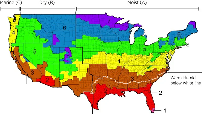
A code-ready envelope begins with the requirements that actually apply to the project and carries those requirements through the drawings, specifications, and field details. “Code-ready” isn’t an official IECC or ASHRAE term. Here, it means designing to the current code with room to adapt. The first decisions are the adopted code or standard, the project climate zone, and the compliance method the design team intends to use. A complete enclosure also has to function as a system, which is why building envelope systems should be designed with walls, roofs, openings, insulation, and moisture-control components coordinated before individual details are finalized.
Those decisions shape the criteria that follow, including insulation levels, assembly thermal values, glazing limits, air-control provisions, and documentation. The newest published model code does not automatically govern every project because states and local jurisdictions adopt and amend codes on their own schedules. Start with what your jurisdiction has actually adopted.
Is R-Value Enough to Demonstrate Envelope Performance?
R-value alone does not describe how the full assembly handles heat flow.
R-Value and Assembly U-Factor
R-value is the thermal-resistance metric used for insulation requirements in the prescriptive path. U-factor evaluates heat transmission through the assembly as a whole, allowing framing and other conductive components to be reflected in the assembly value.
The difference matters because a wall is more than its insulation. Framing, structural elements, fasteners, clips, and other materials can influence the thermal behavior of the finished assembly even when the specified insulation itself meets the required R-value.
Where Continuous Insulation Fits
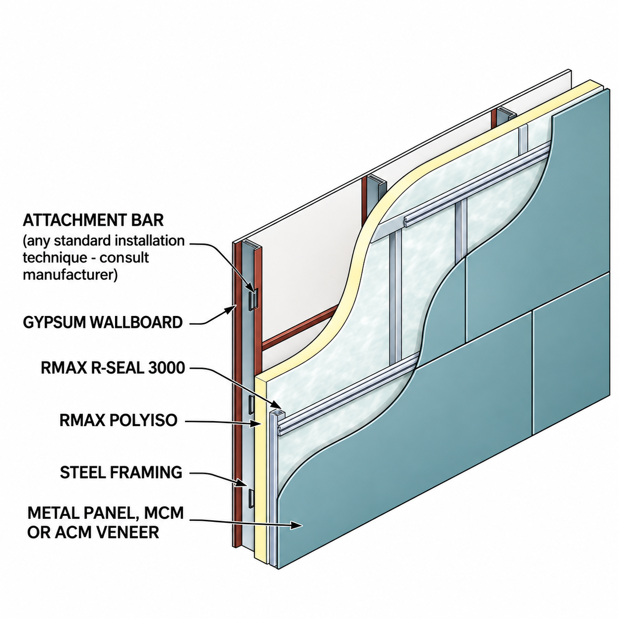
A continuous-insulation layer spans the framing plane instead of stopping at individual framing cavities. By adding thermal resistance over the framing itself, it can reduce repetitive framing losses and improve whole-assembly thermal performance.
Project-specific continuous insulation code requirements should be evaluated after the wall type, climate zone, and compliance method are established. Some prescriptive wall configurations include a continuous insulation layer, while other assemblies may satisfy the applicable criteria through assembly U-factor or another permitted approach. In other words, CI is one tool in the compliance strategy, not a blanket requirement.
Which Compliance Path Fits the Project?
The correct compliance path depends on the governing code or standard and the type of analysis the project team chooses to use. That choice should be established before final wall assemblies are locked in because the required calculations and documentation differ by path. For commercial opaque assemblies, the 2024 IECC, and earlier versions include prescriptive insulation R-value requirements , U-, C-, and F-factor methods, and a component performance alternative.
ASHRAE 90.1 also provides prescriptive envelope requirements and allows other approaches, including an envelope trade-off method and modeled performance methods. Designers should identify the selected path in the project documentation so reviewers, contractors, and substitution requests can be evaluated against the same basis.
Where Do Thermal Bridges Change Assembly Performance?
Thermal bridges show up in two ways: in a repeating pattern across the wall, and at specific connections.
Repeating Conditions Within the Wall
Framing members and other regularly spaced components create recurring conductive paths through a wall assembly. Exterior insulation can reduce the effect of those paths by adding thermal resistance outside the framing plane.
An energy efficient building envelope is judged by how the whole assembly performs, not by the insulation label. Material selection, framing layout, attachment methods, and surrounding control layers all contribute to the result.
Localized Connections and Interfaces
Some thermal losses are concentrated at specific details rather than repeated across an entire wall. Slab and floor edges, parapets, balconies, shelf angles, structural members, cladding attachments, and window or door perimeters are examples of locations that can deserve separate review.
Depending on the assembly, the response may involve revising the attachment configuration, adding insulation around the connection, or selecting a detail with documented thermal performance. These spots can leak heat even when the wall around them meets its insulation target. The design team should identify which interfaces are significant under the governing code or standard and show how those conditions are handled in the construction documents.
How Are Newer Codes Treating Interface Losses?
Recent model codes and standards give greater attention to heat flow at building-envelope interfaces. ASHRAE 90.1-2022 added prescriptive requirements in Section 5.5.5 addressing linear and point thermal bridges, subject to the section’s scope, exceptions, and applicable compliance method. ASHRAE has since released 90.1-2025, but the thermal-bridge provisions first appeared in the 2022 edition. Which edition applies to your project depends on local adoption.
The 2024 IECC also includes prescriptive thermal-bridge requirements for above-grade walls in Section C402.7; the 2027 IECC addresses this in greater detail. It has its own applicability rules and options, so read it alongside the rest of the commercial envelope requirements. These changes require project teams to examine selected junctions alongside broad wall insulation values. The code or standard adopted by the authority having jurisdiction still determines what is enforceable for a specific project.
Where Do Control Layers Need the Most Coordination?
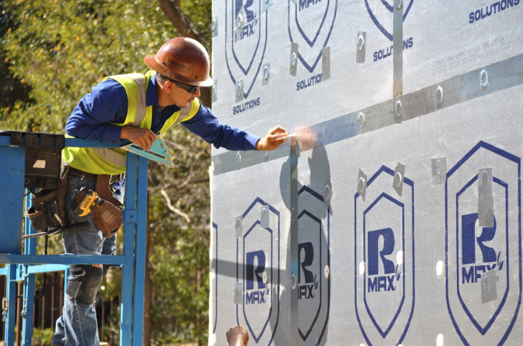
Most coordination problems happen where materials stop, turn a corner, or meet another system. If the code requires a continuous air barrier, it has to stay continuous through those spots too.
Openings and Fenestration
Windows and doors bring insulation, flashing, air control, water management, and structural attachment into one compact area. Applicable energy-code provisions may also establish air-leakage criteria, so the enclosure strategy has to address leakage performance along with continuity at openings and adjacent construction.
Fenestration must also satisfy the thermal criteria associated with the selected compliance path. Depending on the project, those criteria may include U-factor, solar heat gain coefficient, and limits on fenestration area.
Penetrations and Attachments
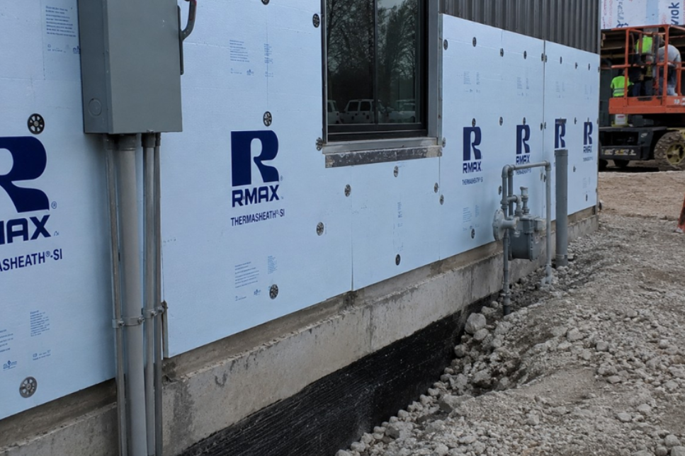
Service penetrations and attachment points can affect several enclosure layers at once. Pipes, conduits, anchors, brackets, and cladding supports should be detailed so the project team knows how applicable insulation, air-control, flashing, and sealing details are maintained around each interruption.
Field substitutions deserve particular scrutiny when they change the attachment geometry or add new penetrations. A substituted detail may affect thermal performance or control-layer continuity even when the visible finish remains the same.
Roof, Floor, and Wall Intersections
Roof-to-wall connections, parapets, wall bases, floor lines, and roof-edge conditions often bring several materials and trades into the same detail. The drawings should establish how insulation, drainage components, flashing, air-control materials, and adjacent assemblies connect through the change in construction. Moisture control at these intersections also depends on coordinating drainage, flashing, vapor control, and drying potential with the selected assembly.
Sequencing also matters because one trade may need access before another component is installed. Clear drawings and defined responsibilities reduce the chance that a key connection will be left unresolved until the enclosure is already being closed.
Code-Minimum Envelope Vs. High-Performance Code-Ready Envelope
A code-minimum design satisfies the requirements applicable to the project and provides increased energy efficiency. A code-ready approach adds greater attention to assembly behavior, interface conditions, documentation, and adaptability where project goals justify it.
| Category | Code-Minimum Approach | High-Performance / Code-Ready Approach |
|---|---|---|
| Insulation strategy | Meets the applicable thermal criteria | Evaluates nominal insulation together with assembly behavior |
| Thermal bridging | Addresses conditions required by the selected code path | Reviews recurring and localized conductive paths during design |
| Continuous insulation | Included where required or selected | Applied strategically where it improves the assembly |
| Air-barrier continuity | Satisfies applicable air-control provisions | Coordinates required continuity details across drawings, submittals, and field execution |
| Wall thickness | Based on the compliant assembly | Balanced with performance targets, constructability, and future flexibility |
| Air leakage | Meets applicable code requirements | May pursue tighter leakage performance or additional project-specific quality controls that exceed the governing minimum |
| Moisture management | Meets applicable assembly requirements | Coordinates drainage, vapor control, drying potential, and insulation |
| Fenestration | Meets applicable thermal and area criteria | Coordinates glazing selection with surrounding enclosure details |
| Detailing | Documents compliant construction | Gives additional attention to complex interfaces and field conditions |
| Energy performance | Meets the applicable code criteria | Pursues stronger enclosure performance through coordinated assembly design |
| Future adaptability | Designed around current adopted requirements | Leaves more flexibility if future project or code targets become stricter |
Designing past the minimum buys flexibility, but no design can guarantee compliance with a code that hasn’t been written yet.
How Can Teams Design for Future Code Changes?
Teams can prepare for tighter energy code requirements and increased energy efficiency by building flexibility into the enclosure design rather than attempting to predict the exact contents of a future code. Early attention to assembly heat flow, interface conditions, air control, and documentation gives the project a clearer technical baseline if performance targets change later.
The process should still begin with the code currently adopted for the project. Once compliance is established, the team can decide if additional insulation, improved interface treatment, tighter air-control detailing, or other measures are appropriate for the owner’s goals.
Energy-Code Ready Building Envelope Checklist
Before finalizing an energy code building envelope, confirm that the design team has addressed each of the following:
Applicable code edition: Identify the code or standard and any local amendments governing the project.
Climate zone: Confirm the correct climate zone before selecting thermal and fenestration criteria.
Compliance path: Record the prescriptive, component-performance, envelope trade-off, or modeled method being used and the applicable R-, U-, C-, or F-factor criteria.
Insulation R-value: Verify the required insulation levels for each opaque assembly where the selected path uses prescribed R-values.
Assembly thermal performance: Check the applicable U-, C-, or F-factor limits when those methods are used.
Continuous insulation: Determine if the selected wall or roof assembly calls for a continuous insulation layer and how that layer fits the overall design.
Recurring conductive paths: Review framing and regularly spaced components that affect assembly heat flow.
Localized thermal bridges: Evaluate conditions such as slab and floor edges, parapets, balconies, shelf angles, cladding supports, structural connections, and opening perimeters where required.
Continuous air barrier: Identify the required air-control plane and show how its materials or assemblies connect across adjoining portions of the enclosure.
Air sealing: Define the treatment of joints, material changes, service openings, and other locations that could permit unintended airflow.
Transitions, openings, and penetrations: Show how enclosure layers continue or reconnect where assemblies change, and around windows, doors, services, anchors, and other interruptions.
Moisture control: Coordinate flashing, drainage, vapor control, drying potential, and insulation with the selected assembly.
Fenestration: Verify the thermal and area requirements that apply to windows, glazed doors, and other fenestration under the selected compliance path.
Compliance documentation: Record required assembly values, calculations, assumptions, and key details so the basis of compliance is clear.
Field verification: Review substitutions and installed conditions against the approved design before critical work is concealed.
Build a More Coordinated Envelope With Rmax
Rmax polyiso products can support exterior continuous insulation strategies in wall and roof assemblies that call for rigid insulation. Rmax’s technical team can help match the right product to your assembly and code path. Contact us today to talk through your project.
Frequently Asked Questions
These questions address several practical decisions that arise during commercial envelope design.
-
No. Whether continuous insulation is required depends on the governing code, climate zone, framing system, assembly, and selected compliance path.
-
Yes, when the governing code provides a U-factor compliance method for the assembly in question. The design must meet the applicable assembly limit and follow the documentation requirements associated with that method.
-
No. Future editions can change thermal limits, testing requirements, documentation, compliance methods, and other provisions, so added performance today can improve adaptability without guaranteeing future compliance.