Moisture management in CI Wall Systems happens at the assembly level. Rain, air leakage, vapor movement, and temperature all shape the result. When those layers line up, continuous insulation can help keep sheathing warmer, reduce thermal bridging, and put the wall in a better position to limit dampness that can lead to mold and long-term durability problems.
How Moisture Moves Through a CI Wall Assembly
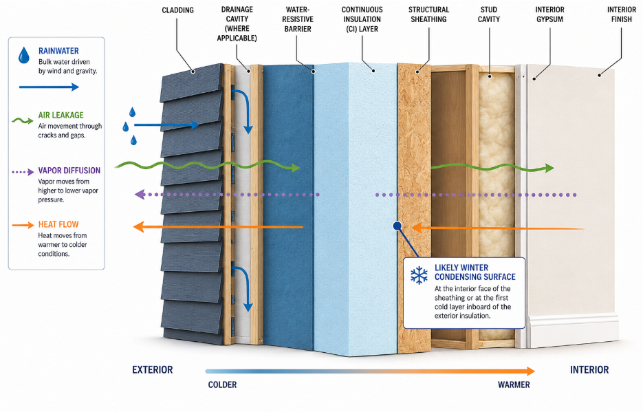
Wall assemblies usually face four main moisture transport mechanisms: bulk water intrusion, capillary movement, air-transported moisture, and vapor diffusion. Condensation is the result that occurs when moisture reaches a surface cold enough to fall below the dew point inside the assembly. Bulk water usually enters at failed laps, missing flashing, and transitions, while winter condensation often starts when humid indoor air reaches a cold surface within the wall.
Air leakage deserves special attention because it can move much more moisture than vapor diffusion in cold-weather wall failures. Vapor retarders slow diffusion, but they do not take the place of a continuous air barrier. That matters in CI walls because sealed board joints only carry part of the load. The assembly still depends on clean continuity at seams, penetrations, and transitions.
Moisture Management in CI Wall Systems and the Role of Control Layers
CI changes moisture performance by warming key layers, but the wall still needs each control function assigned clearly.
How Exterior CI Changes Sheathing Conditions
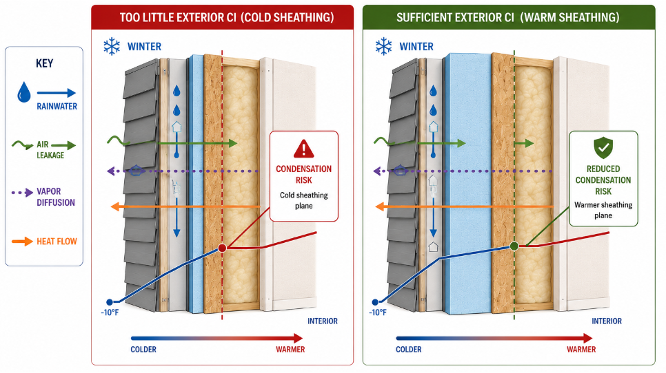
Continuous insulation changes the thermal profile of the wall because it moves more of the total R-value to the exterior side of the framing. That keeps the structural wall warmer during cold weather. A warmer sheathing layer is less likely to collect condensation from interior moisture, which is why exterior insulation is tied so closely to durability in cold-climate wall design.
Why Control-Layer Assignment Still Matters
Rmax also presents CI as a layer that can support several enclosure functions within a high-performing wall system. Its CI guidance says the assembly may contribute to water-resistive performance, air-barrier performance, and moisture-vapor control depending on the product configuration and system design. That flexibility only helps when the team is clear about which layer is doing what, and how that control continues across the elevation.
CI’s real design value is that it lowers thermal stress at framing interruptions and helps protect temperature-sensitive layers, while flashing discipline, drainage planning, and transition detailing still control whether incidental water leaves the assembly quickly or stays long enough to damage materials.
Common Moisture Failure Points in CI Wall Systems
In practice, moisture management in CI wall systems often breaks down first at openings, transitions, and penetrations where control layers lose continuity. Most field problems do not begin in the middle of a clean wall field. They begin where control layers change direction or get interrupted. Window perimeters, door heads and sills, base-of-wall conditions, roof-to-wall intersections, deck attachments, service penetrations, and cladding support points all introduce opportunities for water entry and air leakage if the WRB, flashing, and air-control layers are not tied together cleanly.
The risk increases when a wall relies on taped or sealed CI joints for part of its air or water control and then loses continuity at a transition. A well-performing field of boards cannot compensate for a weak opening detail or an unsealed penetration. That is why Rmax highlights windows, doors, roof intersections, flashing, and moisture barriers as installation priorities in CI wall design.
Comparison Table: Moisture Pathways and Detailing Responses
| Moisture Pathway | Typical Problem Area | What CI Changes | Required Detailing Response |
|---|---|---|---|
| Bulk water intrusion | Openings, laps, roof-to-wall transitions | Keeps the thermal layer continuous but does not stop water on its own | Continuous WRB, shingle-lapped flashing, drainage exit paths |
| Air leakage | Board seams, penetrations, attachment points | Sealed joints can help reduce airflow through the wall | Continuous air barrier, sealed penetrations, transition continuity |
| Vapor diffusion | Interior finish to colder exterior layers | Exterior CI changes temperature profile and drying behavior | Climate-appropriate vapor retarder and permeance strategy |
| Condensation | Sheathing plane in cold weather | Warmer sheathing reduces condensing potential | Adequate exterior-to-interior insulation ratio and airtight execution |
Material Selection, Vapor Permeance, and Drying Strategy
Drying strategy works best when the wall’s permeance profile and climate response are planned together.
Climate and Vapor-Control Strategy
Vapor control should be selected as part of the full wall stack. It has to follow climate, layer arrangement, and interior vapor-retarder strategy rather than a one-size-fits-all rule. Drainage and vapor-control decisions also vary with climate and cladding conditions.
Facer Selection and Drying Direction
That matters because CI products and facers do not all behave the same way. Rmax states that polyiso continuous insulation facer options can be selected either for WRB performance or for water-vapor permeability depending on climate and code-driven design preferences. A hot-humid wall, a mixed-climate wall, and a cold-climate wall may all need different drying priorities, even when the project team is using continuous exterior insulation in each case.
In practice, moisture management in CI wall systems improves when the team decides early which direction the wall should dry under expected conditions and then avoids trapping moisture between low-perm layers. In cold climates, assemblies often aim to protect the sheathing by keeping it warm and controlling interior vapor carefully. In hot-humid climates, assemblies often place more emphasis on managing inward vapor drive from wet claddings and reservoir materials. When moisture accumulates anyway, real-world thermal performance can drop because wet materials no longer behave like a dry, well-detailed assembly.
Climate-Zone Recommendations for Condensation Control
Climate-zone guidance is most useful when it explains the design priority without pretending one ratio works everywhere.
How Climate Changes Condensation Risk
Climate changes the level of condensation risk because it changes how long the sheathing stays cold and how much vapor pressure the wall sees during the year. In colder climates, the wall needs enough exterior insulation to keep the condensing surface warm enough. A commonly cited Zone 5 example for a 2x6 wall with a Class III interior vapor retarder uses at least R-7.5 exterior insulation under IRC Table R702.7.1.
That example applies to a framed wall using a Class III interior vapor retarder, and final project requirements still depend on the adopted code path and the specific assembly. The design direction is still clear: colder zones usually need tighter control of exterior R-value, and warm-humid zones usually need closer attention to rain control, inward vapor drive, and drying behavior.
Climate-Zone Recommendation Table
| Climate Grouping | Main Moisture Concern | CI Design Priority | Verification Point |
|---|---|---|---|
| Zones 1–3 | Rain control and inward vapor drive | Coordinate cladding drainage, WRB continuity, and drying path | Confirm the vapor-retarder approach is permitted and does not trap seasonal moisture |
| Zone 4 / Marine 4 | Mixed drying conditions | Balance exterior insulation, airtightness, and permeance | Review wall drying direction and reservoir-cladding exposure |
| Zones 5–8 | Cold-weather condensation at sheathing | Maintain enough exterior CI to keep the condensing surface warmer | Verify the exterior-to-interior insulation ratio and vapor-retarder path against the adopted code |
Installation Practices That Protect Moisture Performance
Good ratios and material choices still have to survive the jobsite if the wall is going to perform as designed.
Execution Details That Protect the Design Intent
Those climate and ratio decisions still depend on field continuity at seams, penetrations, and flashing transitions. Installation quality decides whether the designed moisture strategy survives contact with the jobsite. The designated air-barrier layer needs sealed joints, seams, gaps, intersections, and penetrations, and drainage space has to be located correctly where the wall design requires it. Rmax’s CI guidance makes the same point in application terms, emphasizing sealed seams, continuous coverage, and careful interface coordination.
Field sequencing, inspection, and trade handoff decide whether continuous insulation moisture control actually holds up on the wall. If flashing is installed out of order, if boards are fastened over irregular substrates, or if the transition from CI to opening flashings is left ambiguous, the wall can lose the moisture margin that exterior insulation was meant to create. Good CI design has to carry through field sequencing, inspection, and handoff between trades.
Best-Practice Checklist
☐ Define which layer is the primary WRB and which layer is the primary air barrier before detailing begins.
☐ Keep flashing tied back to the designated WRB at windows, doors, base-of-wall conditions, and roof transitions.
☐ Treat board joints, penetrations, and interface changes as high-risk locations, even when the field area is straightforward.
☐ Verify that the vapor-control strategy matches the climate and does not create a trapped-moisture condition.
☐ Check the exterior-to-interior insulation ratio before relying on a Class III interior vapor retarder in colder zones.
Why Early Coordination Protects Moisture Performance
CI also supports energy performance because it reduces thermal bridging through studs, plates, and other framing interruptions.
Because of that, detailing, sequencing, and product coordination have to stay tied to moisture management in CI wall systems from the start of enclosure design. When those decisions are aligned, the wall is better positioned to dry as intended and avoid the long-term moisture accumulation that drives mold risk, material damage, and hidden assembly failures.
Specify Rmax Continuous Insulation for Durable Wall Performance
Rmax CI products give design teams a way to maintain thermal continuity while coordinating moisture-related control layers across the wall assembly. Careful facer selection, clean transition detailing, and climate-appropriate drying strategy all help support more reliable in-service performance. Contact us today for more information.
Frequently Asked Questions
-
It means coordinating drainage, air control, vapor control, and exterior insulation so the wall can dry properly and keep condensation-sensitive layers warmer.
-
Not by default, because the assembly still needs clearly assigned control layers and sealed transitions, even when CI can contribute to WRB or air-barrier performance.
-
Exterior CI helps by keeping the sheathing warmer, which lowers the chance that interior moisture will condense inside the wall during cold weather.
-
They usually start at openings, penetrations, flashing transitions, and other points where the wall’s control layers lose continuity.
-
Yes. Colder zones require closer attention to exterior-insulation ratio for condensation control, while warmer or mixed climates require closer attention to rain control, inward vapor drive, and drying direction.