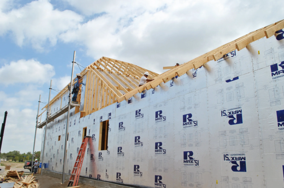
A wall can be ready for cladding and still contain defects that no one will see again without removing finished work. Open joints, crushed boards, missed framing, or incomplete flashing transitions can trigger rework, delay inspection, and weaken the assembly the design team approved. A planned continuous insulation installation process gives crews and inspectors specific points to catch those problems before the wall is covered.
How Field Conditions Affect Whole-Wall Performance
The specified wall assembly establishes the intended thermal performance. Poor fit, attachment errors, and unresolved gaps can weaken thermal continuity. When a facer is part of the air- or water-control strategy, damage can compromise that function. Fasteners, cladding supports, air leakage paths, and transition details also influence whole-wall performance, so quality control must evaluate the completed assembly rather than the insulation boards alone.
During continuous insulation installation, the most consequential defects often appear where several systems meet. Window openings, roof-to-wall transitions, shelf angles, penetrations, and changes in substrate require close coordination because several enclosure layers and structural connections meet in a small area.
What to Verify Before Installation Begins
Unclear details, conflicting documents, and unresolved attachment questions often become field problems after installation starts. Crews, inspectors, and designers should work from the same approved assembly, installation sequence, and review criteria.
Approved Documents and Responsibilities
Review the drawings, specifications, approved submittals, product data, shop drawings, and attachment requirements that apply to the wall area. Confirm that field personnel have access to the current documents and understand who inspects the work, who approves repairs, and who authorizes concealment.
Rmax publishes system-specific installation instructions for different products, attachment methods, joints, penetrations, rough openings, corners, and flashing conditions. Those instructions should be coordinated with the project documents rather than treated as a substitute for them.
Material Delivery and Storage
Confirm the product name, thickness, facer, quantity, and visible condition against the approved submittals when materials arrive. Boards that are crushed, warped, wet, punctured, delaminated, or otherwise damaged should be set aside until their condition has been reviewed.
Store materials according to the applicable instructions and protect them from weather, traffic, and other site conditions that could damage them. Confirm any product-specific limits for weather exposure, temporary protection, and the timing of subsequent wall layers. Catching the wrong thickness or facer at delivery can prevent the installation of nonconforming boards.
Substrate Readiness
Inspect the receiving surface before installation begins. The substrate should be ready to support a flat, secure installation and should not contain debris, protrusions, unresolved damage, or incomplete work that conflicts with the specified details.
Differences between field conditions and the drawings should be resolved before insulation covers them. A first-work review or mockup lets the project team correct layout, attachment, transition, or sequencing problems before crews repeat them across an elevation.
Continuous Insulation Installation Checklist
The active-installation portion of a CI installation checklist should verify board placement, attachment, joints, facers, openings, penetrations, and transitions as the work progresses.
Board Layout and Fit
Confirm the specified board orientation, layout, and required joint alignment or staggering.
Fit boards closely without forcing, crushing, or deforming them.
Inspect corners, changes in plane, and changes in insulation thickness.
Check cut pieces for adequate support and compliance with the project details.
Protect exposed edges and facers from damage during ongoing work.
Fastening and Attachment
Compare fastener type, length, spacing, and substrate engagement with the attachment requirements.
Inspect washers or plates where they are specified.
Identify overdriven or underdriven fasteners that crush the insulation, damage the facer, or leave boards loose.
Coordinate clips, brackets, furring, girts, and other cladding supports with the attachment design.
Pause that area of work when framing locations or substrate conditions differ from the design assumptions.
Joints and Facer Condition
Inspect board joints for the required fit, alignment, and treatment shown in the specified system details.
Confirm that tapes, sealants, and flashing materials are approved for the selected system and condition.
Review tears, punctures, delamination, crushed edges, and field repairs while the area remains accessible, and keep repaired areas open until the correction has been accepted.
Openings, Penetrations, and Transitions
Coordinate insulation and flashing at windows, doors, louvers, service penetrations, and other openings before cladding advances.
Review corners, parapets, floor lines, balconies, shelf angles, and roof-to-wall transitions.
Confirm continuity where the substrate, control layer, or insulation thickness changes.
Verify that temporary work or later trade activity has not damaged completed areas.
CI Installation Best Practices vs. Common Mistakes
The comparison below connects observable field conditions with the problems they can create. Use it as a quick field reference alongside the specified assembly and manufacturer instructions. Each condition should be evaluated against the project details and attachment requirements.
| Inspection Area | Best Practice | Common Mistake | Potential Consequence |
|---|---|---|---|
| Materials | Match the product, thickness, and facer to approved submittals | Install an incorrect board or unreviewed substitute | Removal, delay, or departure from the approved assembly |
| Substrate | Resolve surface and coordination problems before covering them | Install over debris, protrusions, damage, or incomplete work | Uneven boards, poor support, or concealed conflicts |
| Board Joints | Follow the required fit, alignment, and treatment | Leave open, irregular, or unsupported joints | Interrupted thermal continuity and difficult transition detailing |
| Fasteners | Follow the required type, spacing, engagement, and attachment components | Overdrive, underdrive, or miss the intended support | Board damage, loose areas, or attachment concerns |
| Rough Openings | Coordinate insulation with flashing and adjacent control layers | Complete one layer without resolving the others | Discontinuous thermal, air, or water control |
| Penetrations | Detail and inspect service openings before concealment | Leave gaps around pipes, ducts, or conduit | Hidden discontinuities and later removal work |
| Repairs | Follow the accepted repair method and reinspect the area | Apply an improvised repair without review | Unverified material or control-layer performance |
| Documentation | Record locations, photographs, corrections, and closure | Rely on memory or verbal confirmation | Missing evidence after the condition is concealed |
Quality-Control Practices That Catch Problems Early
Effective continuous insulation quality control identifies what must be checked, who performs the inspection, and when the work must remain accessible. A final walkthrough cannot reliably verify joints, fasteners, flashings, and repairs that are already covered.
Inspect the First Completed Area
Review the first representative wall area before crews repeat the same detail. This inspection can identify layout errors, attachment conflicts, damaged facers, or incomplete transitions before they spread across the project.
Include the installer and the project representatives responsible for resolving detail questions or approving corrective work. The contract documents and quality-control plan should identify the parties assigned to those roles.
Establish Inspection Hold Points
Set hold points for conditions that will become inaccessible, especially flashing, attachment changes, repairs, and control-layer transitions.
Each hold point should identify who must inspect the work and what record is required before installation proceeds. A pipe penetration that is easy to correct today may require cladding removal once it is covered. Catching repeated defects early can also reduce rework and lower the risk of callbacks.
Document Deficiencies and Corrections
Record the location, date, condition, responsible party, required action, and reinspection status for each deficiency. Photographs should show the original condition and the completed correction when project procedures require visual records.
The record should remain open until the correction has been reinspected and accepted. Those records give building owners documentation of the inspections and corrections completed before turnover.
Coordinate CI With Air, Water, and Cladding Systems
Joints, openings, flashing transitions, and cladding attachments are common locations for insulation continuity to break down.
Control-Layer Responsibilities
The approved wall assembly assigns responsibility for thermal, air, water, vapor, and structural functions. The insulation should be treated as an air barrier or water-resistive barrier only when the selected system and project details assign that role.
Not every CI system requires taped joints. Joint treatment, flashing, sealants, and transition materials must follow the specified assembly and applicable manufacturer instructions. Continuous insulation systems may contribute to several enclosure functions, but field crews still need clear direction about which layer controls each function at joints, openings, and changes in plane.
Cladding Attachment Coordination
Cladding fasteners, clips, furring, and brackets must follow the approved load-transfer design. Their installation should also preserve required air-, water-, and thermal-control transitions. Insulation thickness changes the relationship between the cladding and its structural support, so fastener length, spacing, cladding weight, and backup framing must remain coordinated with the attachment design.
Building Code and Compliance Considerations
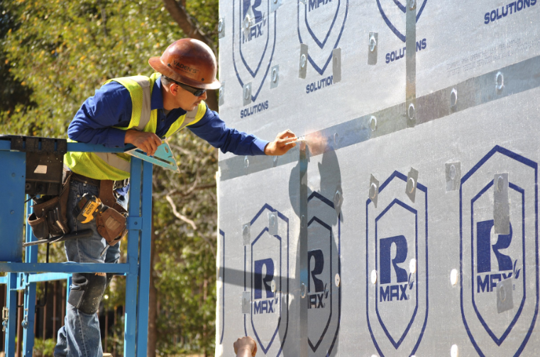
A continuous insulation installation checklist supports compliance by helping the project team verify that installed work follows the approved construction documents and applicable instructions. It does not establish compliance by itself.
Applicable continuous insulation code requirements vary with the adopted code, climate zone, wall type, material, and selected compliance path. The controlling requirements come from the code adopted by the jurisdiction and the wall assembly approved for the project. Field substitutions, altered attachment conditions, and changed transition details may require review before work continues, and those field changes should be recorded so the completed wall can be compared with the approved design during closeout.
Corrective Action Before Concealment
Corrections should follow a consistent process:
Record the exact location and visible condition.
Compare the condition with the approved requirement.
Keep unresolved work accessible.
Obtain direction when the repair method is unclear.
Complete the accepted correction.
Photograph or otherwise document the finished repair.
Reinspect the area.
Close the deficiency record.
Without reinspection and closure, a temporary field repair can become an undocumented part of the wall.
Final Inspection Checklist
Before cladding or later work conceals a completed continuous insulation installation, the final review should confirm the physical work and supporting records.
Installed Work
Confirm the correct product, thickness, and complete coverage across the inspected area.
Verify that boards remain flat, secure, adequately supported, and free of unresolved damage or repairs.
Confirm that joints match the specified system requirements.
Verify that fasteners, plates or washers, and cladding-attachment components match the attachment requirements.
Confirm that rough openings and penetrations are complete.
Verify corners, transitions, and changes in plane.
Confirm that flashing and applicable air- and water-control transitions are complete and properly sequenced.
Documentation and Approval
Confirm that deficiency records are closed.
Verify that required photographs and inspection reports are available.
Confirm that the responsible party has authorized concealment.
Use the CI installation guide with the specified details and inspection records when reviewing the completed work.
Use Rmax Technical Resources to Support Better Wall Coordination
Rmax provides technical literature and installation materials for multiple products, attachment methods, flashing conditions, penetrations, joints, and rough openings. Project teams can use that information to coordinate insulation details with flashing, attachment, and cladding requirements. Contact us today for more information.
Frequently Asked Questions
These field questions usually come back to the selected system, the approved project documents, and what can still be inspected before the wall is covered.
-
The contract documents and project quality-control plan should define responsibility. They should identify who performs inspections, approves repairs, verifies corrections, and authorizes concealment.
-
No universal joint-treatment rule applies. The selected system, assigned control-layer functions, approved details, and manufacturer instructions determine what joint treatment is required.
-
The type, location, and extent of the damage guide whether a board can be repaired or should be replaced. Significant damage or an uncertain repair should be reviewed against the manufacturer’s instructions and project requirements before the board is covered.
-
A few completed conditions may still be visible later, but many joints, fasteners, flashings, and transitions become inaccessible. Staged inspections give the project team a better chance to verify those details before cladding covers them.